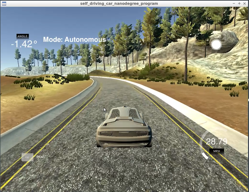
In this blog post, I want to share some of my experiences with Controllers and their applications. My first introduction to PID controllers was in Udacity’s Self Driving Car Nanodegree where we learned to control the car’s steering wheel and speed.
Controllers and the Control Loop
A controller is a device or software that controls the settings of another device to achieve a goal. Let’s look at controlling a car’s speed as an example. Car’s have a gas pedal, a brake, an odometer, and a controller to change the car’s speed. If the controller or driver in this case wants to go 50 mph then the person will press the gas pedal down until the odometer says the car has reached 50 mph. If the car is going faster than 50 mph the driver will either stop pressing the gas or will press the brake to slow down. In this way the car will go the intended speed, but we are interested in automating the controller, so lets move on to the PID controller.
A PID controller is the most common way to design a controller, because it is effective and simple. PID stands for proportional–integral–derivative, and I’ll talk about each part.
Proportional (P)
Continuing with the car’s speed, the proportional part changes the speed in proportion to the difference between the goal and current speed. So when the car is going 50 mph slower than the goal speed the car will accelerate faster than it would if it was going 5 mph under. This makes intuitive sense, and one would be tempted to call it good enough, but the car will reach a point where it oscilates around the goal. See the image below.
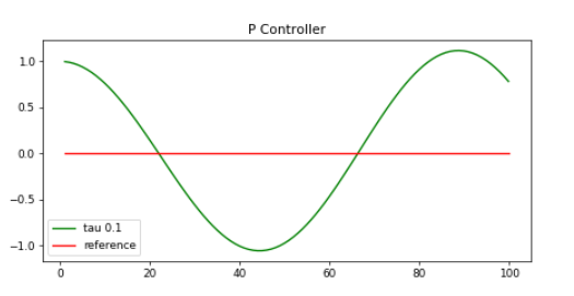
Image shows difference from goal. In the case of speed this 1 +/- mph difference around goal doesn’t seem like a big deal, but minimizing this oscilation can be very important in other applications. One way to minimize it is with tuning because the distance from the goal or error is multiplied by a supplied value called tau. See in the above image how tau was set to 0.1? Below are some examples of how adjusting tau changes the behavior.
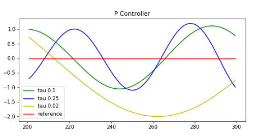
As you can see, as tau gets smaller the controller adjusts its speed much more slowly which causes the longer oscilations.
Below is what the p part of the controller looks like in my code.
// P part of PID Controller
// Kp is the p tau while p_error is the proportion error.
totalError = (-Kp * p_error);
Derivative (D)
To further improve the controller we will implement the other parts of the PID controller. We will skip the Integral portion for now, so the derivative part of the equation takes the derivative of the car’s speed and subtracts it from the proportional value. This works to smooth the oscillations until the point where the car aligns itself with the goal.
// PD controller
// Kp = p tau
// Kd = d tau
p_error = cte; //proportional error
d_error = cte - previous_step_cte;
totalError = (-Kp * p_error) - (Kd * d_error)
In a perfect world we would be done, but real world systems have bias or errors. In our case the odometer could be consistently misreading the car’s speed causing the car’s computer to miscalculate how to reach its goal. What’s worse is that the bias or error could change over time with slippery rain conditions. That is where the integral part comes in.
Integral (I)
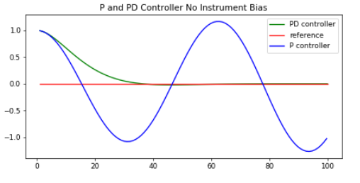
The integral part of the controller takes all of the errors over each time step and sums them up to calculate the integral of the function. So as the device has mistakes in its measurements the accumulating error will cause the controller to correct itself. Below we have a comparison of a PD controller and a PID controller. When the controller has systematic errors the PD controller will behave correctly, but it will be off dependent upon the error. In the chart below it follows the reference line, but it is off by roughly 0.5. With the PID controller it corrects for the error and follows the reference line.

// PID controller
// Kp = p tau
// Kd = d tau
// Ki = i tau
p_error = cte; // error
d_error = cte - previous_step_cte;
i_error = i_error + cte; // i_error steadily changes by adding cte at each time step
totalError = (-Kp * p_error) - (Kd * d_error) - (Ki * i_error);
Summary
So we’ve seen how PID controllers work, and how the different parts are necessary and helpful. It is beautiful in its design and simplicity, and I love using it in projects. In a future blog post I’ll talk about how to find parameters for the PID controller and alternatives.
Below is my submission video for the self-driving car PID project. If I could do it again, I would smooth out the jerky turns, and I would start by playing more with the derivative part of the controller. I was having a hard time getting it to react quickly on the sharp turns while also making it drive smoother. It was my first work with a PID controller, and it could definitely be better. Cheers!